The ability to perform invasive diagnostic coronary angiography is a core requirement for cardiologists and fellows in training programmes. However, although key to their independence is the ability to obtain high-quality images that allow visualisation of the entire coronary vasculature, there exists no formal systematic method or teaching aid. This article provides an overview of the radiological equipment used in the catheter laboratory, details the naming of the different angiographic projections, and gives key tips and tricks to improve image quality. In addition, the coronary vasculature is broken down into segments, with descriptions provided of the essential views required to image each one. Using this approach, it aims to provide an essential aid to trainees and other healthcare professionals at the start of their careers.
Introduction
Invasive diagnostic coronary angiography is a core procedure that all cardiology trainees/fellows are required to learn, and in which they are expected to become independent in practising during their training.1 Learning normally starts during the first year, and a key component of independence is the ability to take high-quality images that are sufficient to image the entire coronary tree, without unnecessary contrast media and radiation use. This requires good technical skills, and knowledge of the factors that influence image quality. In addition, an understanding of the angiographic projections (or radiographic views) required for optimal visualisation of each section of the coronary vasculature is vital. We present an overview of the radiology equipment used in the catheter laboratory and details of how different projections are obtained, together with some simple tips and tricks to optimise images. In addition, by breaking each coronary artery up into key segments, we provide a guide to those projections that are commonly required to ensure complete visualisation of each part of the coronary vasculature. This enables a thorough, complete study to be carried out, but crucially it also aids optimisation of images in the event that a lesion is found. Finally, knowledge of how to obtain optimal images allows operators to limit the number of acquired projections to give sufficient diagnostic information while maintaining the principle of ALARA (‘as low as reasonably achievable’) in relation to radiation exposure. We hope that this will be an essential aid to cardiology trainees/fellows when they first start learning invasive diagnostic angiography, as well as to other healthcare professionals.
Overview
Equipment
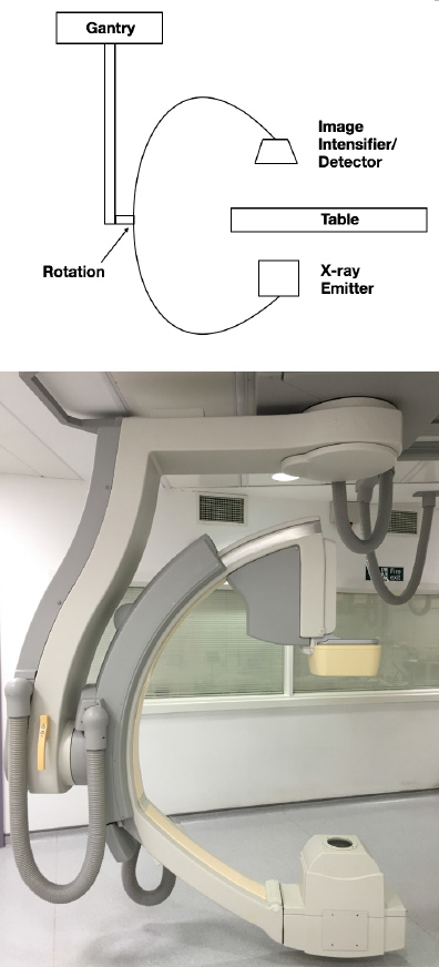
There has been tremendous progress in coronary angiography since the early days, when the X-ray emitter was manoeuvred around the patient in a cradle. Although this allowed images in the transverse plane, wedges were needed to ‘prop’ the patient up for any cranial angulation. Today, the modern catheter laboratory equipment consists of a radiological ‘C-arm’ to overcome this early limitation. In simple terms, this consists of an X-ray emitter at one end of a ‘C’-shaped arm, with an image intensifier at the other end of the ‘C’. The whole C-arm is mobile, therefore, allowing it to be moved around the patient to obtain views from multiple different angulations (figure 1). Latterly, direct digital flat detectors have replaced image intensifiers, improving and providing more consistent long-term image quality. Digital imaging also allows for accurate quantitative measurements (QCA) and transfer of images to appropriate networks for post-processing and, if needed, 3D reconstructions.
doses
Two different imaging modes are available using the C-arm; pulsed fluoroscopy (‘Fluoro’) and cinefluorographic acquisition (‘Cine’). ‘Fluoro’ provides low-resolution real-time X-ray imaging (with resolution measured in pulses/second), allowing observation of the moving coronary tree in the two-dimensional plane. Although image quality can be adjusted by increasing the radiation dose and the pulse rate (normally 10–15 pulses/second in angiography), the generally low-resolution images mean that ‘Fluoro’ is normally used for catheter advancement and manipulation. By contrast, ‘Cine’ (with resolution measured in frames/second) provides images of sufficient quality for single-frame viewing. It is, therefore, used to acquire the angiographic images during contrast media injection. Due to the dynamic nature of the heart and rapid flow down the coronary arteries, frame rates of 10–15 frames/second are generally used for acquisition. ‘Fluoro’ images are, thus, moving images and are not routinely stored, unless specifically requested or done so retrospectively by the operator after acquisition. Due to the higher resolution of ‘Cine’ images, however, the radiation dose needed is approximately 10 times that used in ‘Fluoro’.2 Activation of ‘Fluoro’ or ‘Cine’ is usually via a foot pedal placed next to the operator or radiographer, with a separate pedal for each.
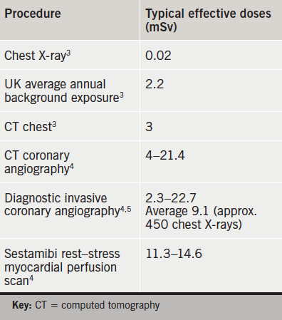
It is important to recognise that angiography does carry significant radiation exposure, which is often not fully appreciated by all operators. This can lead to radiation burns after prolonged exposure in one view. It is, therefore, necessary that, for long procedures, angiographic views are rotated to avoid this complication. The average radiation dose experienced by a patient undergoing conventional diagnostic coronary angiography, along with average doses for other radiographic procedures for comparison, is given in table 1.3-5
Views
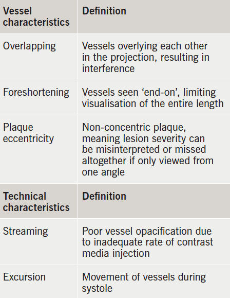
Due to the differing anatomy and positions of the coronary arteries, the X-ray projection required to obtain an optimal view changes according to which section of each artery is being imaged. In addition, because the images obtained are two-dimensional, at least two orthogonal views are normally required for each segment to enable complete visualisation and ensure that eccentric coronary stenoses are not missed. Indeed, the issue of using two-dimensional images to obtain information on a three-dimensional lumen is one of the key limiting factors of conventional angiography.
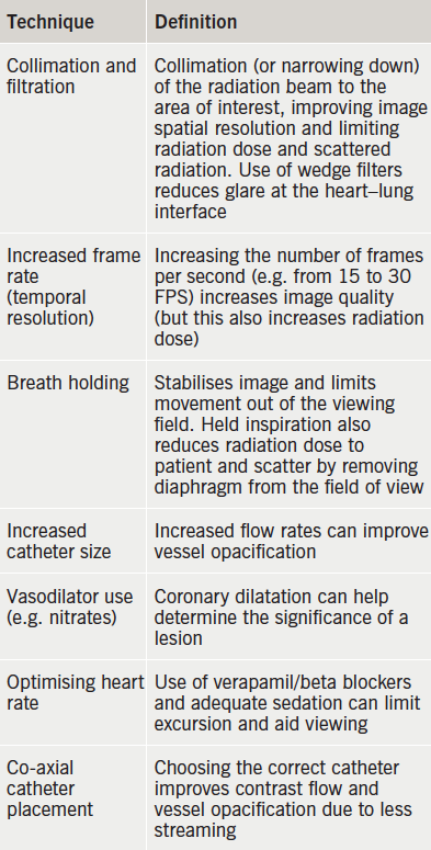
Tables 2 and 3 explain the factors that can affect the images obtained, and how to best optimise these images.
Angiographic views
Angiographic views are classically named after the position of both the X-ray tube and the intensifier (or detector) in relation to the patient. However, they are now commonly simplified to be named according to the position of the image detector alone. When the image is taken, the name is, therefore, where the picture is essentially ‘looking from’ (figure 2).
The main starting position is straight postero-anterior (PA), i.e. directly vertical to the patient’s chest. From here, the ‘C-arm’ can then be moved in two different planes, as follows:
- Right or left anterior oblique (RAO or LAO). The image detector is moved to point at the patient from either the right- or left-hand side, but still lies anterior to the patient. The degree of angulation is given as a figure, e.g. LAO 40o, often shortened to simply LAO 40. If it is moved to the same horizontal level as the patient (i.e. 90o) then the position is called right or left lateral.
- Cranial (Cran) or caudal (Caud). The image detector is moved to point from the head or foot end of the patient, respectively. Again, the degree of angulation is given as a figure in degrees.

The image detector is often positioned at a point that encompasses a combination of these positions, e.g. RAO-Caudal, etc. It is commonly advised that initial cannulation of the right and left coronary ostia is attempted in LAO 40, to help guide initial catheter placement and achieve co-axial alignment. However, some operators prefer PA for the latter. Due to variation of anatomy, the choice of catheter needs to be suitably chosen to avoid the risk of left main stem dissection. Ordinarily, 6F or 5F Judkins right and left catheters are used for diagnostic procedures. 5F catheters have the advantage that they are softer and, hence, less traumatic, but the lower volume of contrast media extruded may limit the image quality. Firmer injections are needed to overcome this limitation. Breath holding is sometimes necessary to achieve successful cannulation, but it is good practice not to engage the ostia straight away but rather perform a non-selective image if there is a suspicion of ostial disease.
The anatomy of the coronary vasculature can be appreciated on 3D reconstructions of computed tomography (CT) coronary angiography (figure 3). In general, the left main stem (LMS) comes off the left coronary cusp and divides into the left anterior descending (LAD) and left circumflex (LCx), while the right coronary artery (RCA) comes off the right coronary cusp. The LAD runs down the anterior interventricular groove, while the RCA and LCx normally run around the heart in the atrioventricular grooves.
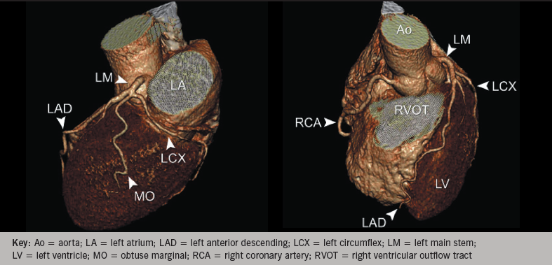
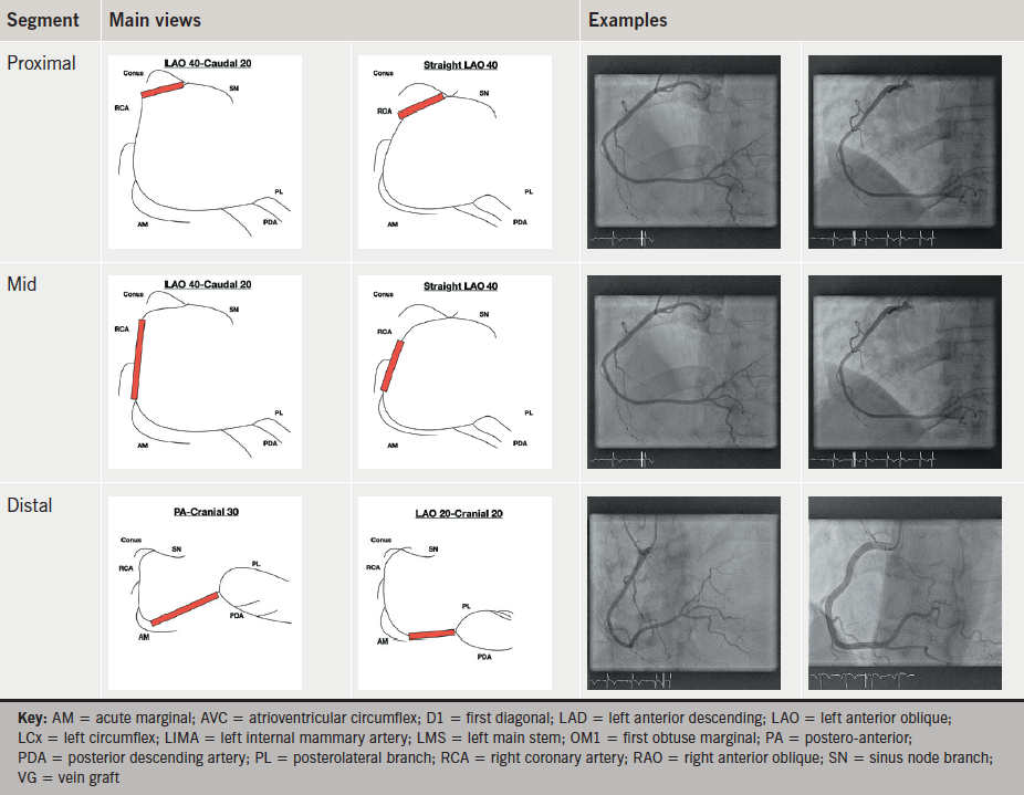
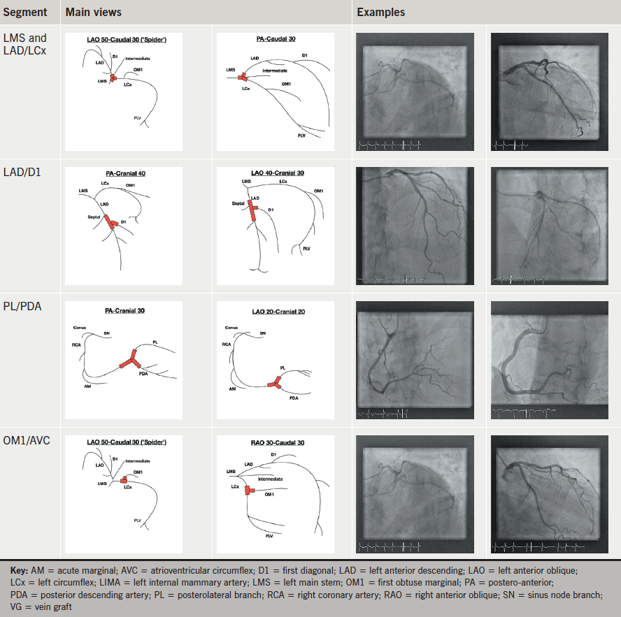
The coronary arteries are then commonly divided into segments for ease of description. Although they can be divided into 16 segments as used in the Syntax Scoring Calculator,6 for optimising angiographic views we have simplified the anatomy into the well-established proximal, mid and distal segments of each coronary artery. Proximal LAD is defined as being between the LMS and the first diagonal (D1).7 Mid LAD is from D1 to the third diagonal (D3) and distal LAD is distal to D3. The LCx is often divided into simply proximal (from LMS to first obtuse marginal [OM1]) and distal (distal to OM1).7 However, we have chosen to define mid circumflex as between OM1 and the second obtuse marginal (OM2) and distal circumflex as distal to this. Finally, the proximal RCA is defined as from the origin to where it becomes vertical, mid as the vertical segment, and distal as from the end of the vertical segment to the bifurcation into posterior-descending and postero-lateral arteries.7
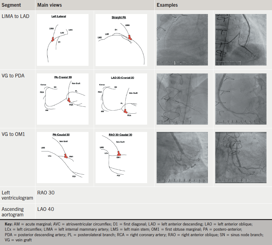
Tables 4a–f gives a list of the most common recommended projections for each coronary segment.8 Although these may well need to be adapted on a case-by-case basis, depending on the anatomy present, and to take into account any patient-specific requirements, they represent the most commonly used projections and are a good starting point when commencing invasive diagnostic angiography for the first time.
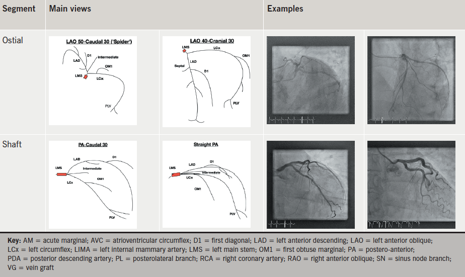
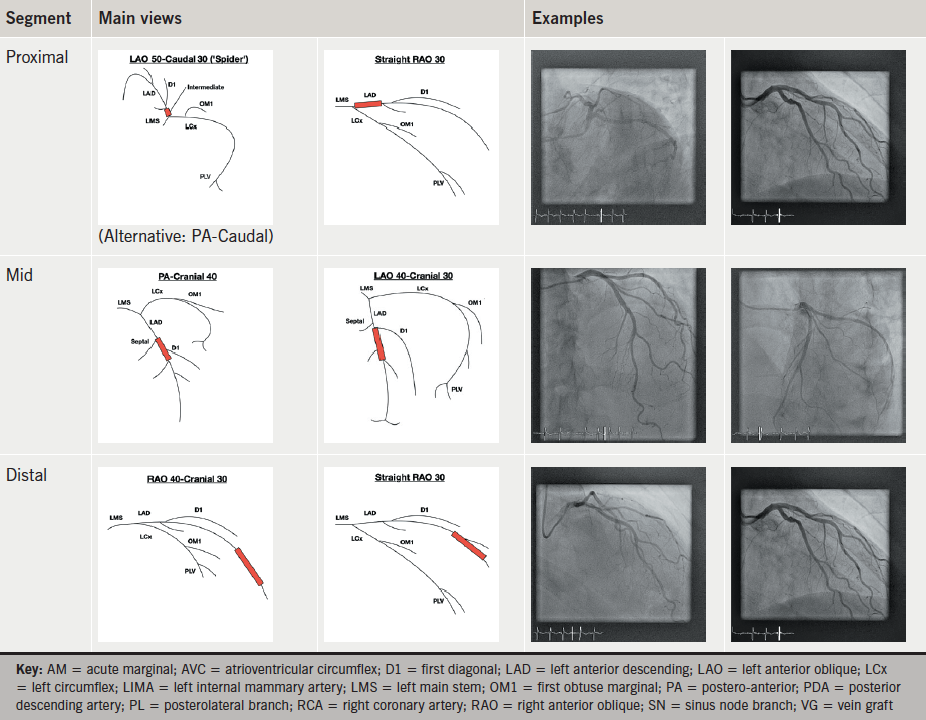
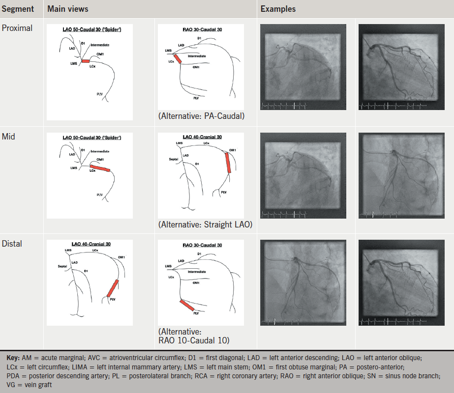
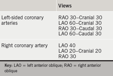
A good standard set of views, which can, therefore, be taken for a straightforward, routine, diagnostic angiogram, and, which are likely to ensure adequate visualisation of the entire coronary anatomy, is given in table 5.9 These can then be adjusted or added to if any particular segment needs further assessment, as per tables 4a–f.
Further techniques
In addition to the common practice illustrated above, there are two other techniques that are sometimes used in coronary angiography. The first of these is biplane angiography, which uses biplane X-ray equipment (essentially like two combined ‘C-arms’) to take simultaneous orthogonal images. This can be especially useful for complex coronary anatomy and for assessing chronic total occlusions (CTOs) and stent position during coronary intervention. In addition, as two images are acquired per injection of contrast media there is a potential for less contrast media use, making it attractive in patients with renal failure. It is also, therefore, useful in left ventricular angiography. However, it requires a radiographer/operator skilled in the use and setting up of biplane equipment and accurate isocentering of the patient, and one study has found that its use in angioplasty can actually result in longer procedure times and increased radiation exposure, with no significant difference in contrast media use.10
The second technique is rotational (or ‘spin’) angiography, in which the ‘C-arm’ is rotated around the patient over the course of a single contrast media injection. Rotations can be linear (e.g. straight LAO to RAO) or elliptical encompassing LAO and RAO projections with varying degrees of cranial and caudal angulation. The techniques rely on accurate isocentering of the patient, stable catheter positions, and consistent injections for the duration of the ‘spin’. Again, this results in less contrast media use and radiation exposure per patient. However, the tradition of standard individual angiographic images means that rotational angiography has failed to become widely used. In addition, some operators may find it more convenient to view and process images individually during the angiogram and then decide on further views required, rather than having to process the information from a rotational acquisition in one go.
Finally, as mentioned above, the limitations of two-dimensional angiography in fully describing coronary lesions make the possible development of new three-dimensional imaging techniques an exciting area.
Conclusion
Learning invasive diagnostic coronary angiography is one of the core skills any cardiology trainee/fellow must acquire early in his/her training programme. Knowing and understanding the different angiographic projections is an essential component of achieving this goal. Here, we present an overview of the radiological equipment used in angiography, details of the different projections and explain how to optimise images obtained during diagnostic coronary angiography. By simplifying the coronary vasculature into three key segments and detailing those projections that are commonly used to obtain complete visualisation of each one, we hope to provide an invaluable guide to trainees when they are starting out in the catheter laboratory.
Conflict of interest
None declared.
Key messages
- Knowledge of catheter lab equipment and coronary anatomy is vital to obtaining optimal diagnostic coronary angiogram images, while limiting radiation exposure and contrast load to the patient
- Breaking the coronary vasculature down into segments when performing angiography helps to ensure that coronary stenoses are not missed
- Optimal imaging of each segment depends on the use of the correct angiographic views
References
1. Joint Royal Colleges of Physicians Training Board. Specialty Training Curriculum for Cardiology August 2010. London: JRCPTB, 2010. Available from: https://www.jrcptb.org.uk/sites/default/files/2010%20Cardiology.pdf
2. Mauro Moscucci. Grossman and Baim’s Cardiac Catheterization, Angiography, and Intervention. 8th edition. Lippincott Williams and Wilkins, 2014. ISBN: 1451127405.
3. Public Health England. Patient dose information: guidance. London: Public Health England, 4 September 2008. Available from: https://www.gov.uk/government/publications/medical-radiation-patient-doses/patient-dose-information-guidance
4. Einstein AJ, Moser KW, Thompson RC, Cerqueira MD, Henzlova MJ. Contemporary reviews in cardiovascular medicine: radiation dose to patients from cardiac diagnostic imaging. Circulation 2007;116:1290–305. http://dx.doi.org/10.1161/CIRCULATIONAHA.107.688101
5. Pantos I, Patakoukas G, Katritsis DG, Efstathopoulos E. Patient radiation doses in interventional cardiology procedures. Curr Cardiol Rev 2009;5:1–11. http://dx.doi.org/10.2174/157340309787048059
6. Sianos G, Morel MA, Kappetein AP et al. The SYNTAX score: an angiographic tool grading the complexity of coronary artery disease. EuroIntervention 2005;1:219–27.
7. Lanzer P, Topol EJ. Pan Vascular Medicine: Integrated Clinical Management. Springer-Verlag, 2002. ISBN: 978-3-642-56225-9.
8. Eeckhout E, Serruys PW, Wijns W et al. Percutaneous Interventional Cardiovascular Medicine: The PCR-EAPCI Textbook. PCR Publishing, 2012. ISBN: 9782913628571.
9. Naber CK, Schmitz T, Meuter K, Sabin GV. Tools and techniques: angiographic views. EuroIntervention 2010;6:424–5. http://dx.doi.org/10.4244/EIJV6I3A70
10. Sadick V, Reed W, Collins L, Sadick N, Heard R, Robinson J. Impact of biplane versus single-plane imaging on radiation dose, contrast load and procedural time in coronary angioplasty. Br J Radiol 2010;83:379–94. http://dx.doi.org/10.1259/bjr/21696839
