Cardiac computed tomography in aortic stenosis
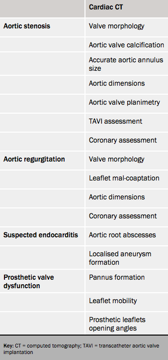
Computed tomography (CT) is not a first-line investigation owing to the need for radiation and contrast and its inability to provide haemodynamic data. However it is indicated:
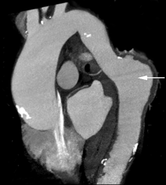
- to measure the diameter of the ascending aorta unless this is well-imaged on echocardiography (see figure 4)
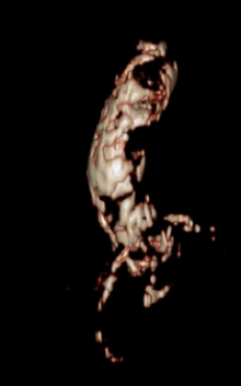
- to assess porcelain aorta (see figure 5, and table 2)
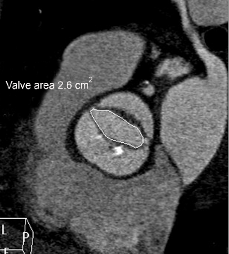
- with suboptimal echo images to image the orifice15 (see figure 6)
- in the work-up towards TAVI16,17
- to assess coronary disease
- to assess aortic valve calcification to help grade equivocal stenosis especially with discordant echocardiographic values.18,19
It is also useful for screening. Aortic valve calcification on a routine non-contrast enhanced CT scan suggests AS and indicates echocardiography.20
Cardiac magnetic resonance imaging in aortic stenosis
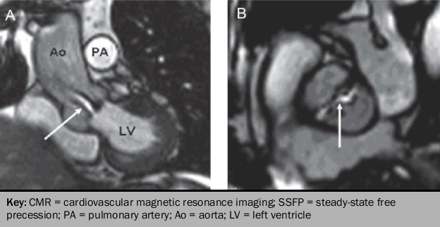
Steady-state free precession (SSFP) cine sequences detect AS from flow turbulence shown as loss of signal due to the dephasing of moving protons.
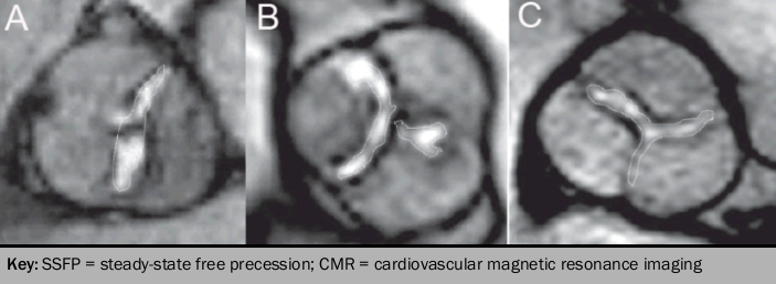
Planimetry of the geometric orifice area using SSFP imaging planes across the aortic valve leaflets correlate well, but systematically underestimates against transesophageal echocardiogram (TEE)21 (see figures 7 and 8). However the complex 3D shape of the stenotic orifice means that accurate visualisation of the true stenotic orifice is not feasible.
CMR may be useful for:
- haemodynamic data if echocardiography suboptimal (using velocity encoded cine phase contrast imaging [VENC] and optimal plane selection at the aortic root, the peak transaortic velocity can be obtained. Peak gradients derived using the Bernoulli equation correlate well, but slightly underestimate the peak gradient obtained with CW Doppler on transthoracic echocardiography [TTE].22
- assessing LV volumes and mass for which it is a recognised ‘gold-standard’
- assessing LV function
- differentiation of sub-valvular and supravalvular stenosis with in-plane velocity mapping
- aortic root geometry and size
- detect myocardial fibrosis using late gadolinium enhancement. This is associated with a poor clinical outcome.23
